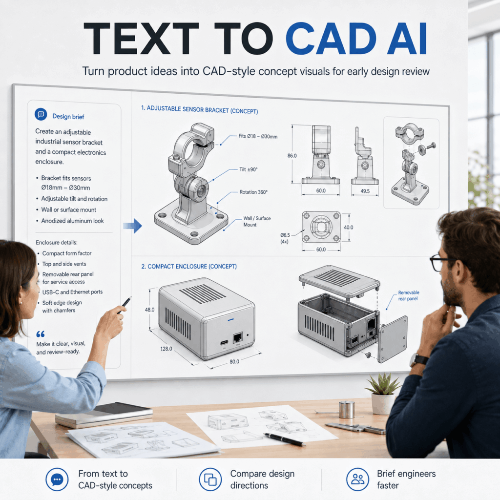
Text to CAD AI gives product teams a practical way to show engineers what they mean before a formal CAD model exists. Instead of relying on vague comments, rough hand gestures, or a long email thread, users can describe a product concept in ordinary language and turn it into a clear CAD-style visual for early review.
For example, a product manager may need an adjustable sensor bracket with slotted mounting holes. A hardware founder may be planning a compact enclosure with ventilation and a removable rear panel. Meanwhile, a client may simply want a device to feel “less bulky.”
Those ideas are easy to say. However, they are much harder to interpret consistently.
Text to CAD AI helps close that communication gap. Users can describe the object’s purpose, overall form, major features, approximate dimensions, assembly context, material direction, and preferred viewing angle. The tool then creates a visual concept that designers, engineers, clients, and other stakeholders can discuss together.
The result is not automatically an editable CAD file or a production-ready engineering model. Instead, it works as an early visual brief. Qualified professionals must still rebuild and verify the final geometry, materials, tolerances, safety, and manufacturability.
Why Text to CAD AI Helps Before Modeling Begins
The first CAD model is rarely created from a perfect brief. More often, an engineer receives a mixture of functional requirements, personal preferences, references, and unclear feedback.
A typical request might sound like this:
We need a compact metal bracket. It should be adjustable, easy to install, and strong enough for industrial use.
Although the general idea is understandable, many important questions remain unanswered.
Where should the mounting holes sit? Should the adjustment use circular holes or elongated slots? Does the arm need a reinforcing rib? Which direction should the fasteners enter from? How much access does an installer need around the bracket?
Without a shared visual reference, each participant may imagine a different solution. Therefore, the first review meeting can quickly turn into a discussion about what the original request was supposed to mean.
Text to CAD AI gives the team something visible to question. A concept visual can reveal the intended proportion, feature placement, mounting direction, and overall product character. As a result, reviewers can respond to a specific direction instead of interpreting the same sentence in several different ways.
This makes the tool useful for:
- Internal product briefs
- Early design reviews
- Client workshops
- Sourcing discussions
- Product proposals
- Prototype planning
- Conversations between technical and non-technical teams
Most importantly, the image does not need to be perfect to be useful. It only needs to make the team’s assumptions visible before expensive engineering work begins.
Text to CAD AI Is a Visual Brief, Not a Final CAD File
The name may suggest that a written prompt instantly becomes a finished engineering model. However, the actual role of Text to CAD AI is more focused.
It turns design intent into a CAD-style concept visual.
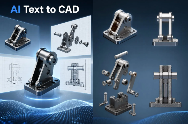
That visual can communicate an object’s overall form, major components, visible interfaces, and possible assembly relationships. It can also show a product through an isometric view, front elevation, exploded concept, section-inspired presentation, or close-up detail.
However, the output should not be treated as:
- An editable STEP file
- A constrained parametric model
- A certified technical drawing
- A complete assembly definition
- A manufacturing dataset
- A structural simulation
- A source of verified dimensions or tolerances
Generated labels and measurements may also be inaccurate. Likewise, hidden geometry may not be complete, and two parts that appear to fit visually may not fit in a real assembly.
Therefore, the concept image should guide questions rather than approve fabrication.
Once a promising direction has been selected, a qualified designer or engineer must rebuild it in appropriate CAD software. They can then define exact dimensions, constraints, materials, interfaces, tolerances, and manufacturing processes.
This distinction does not reduce the tool’s value. In fact, it clarifies where the tool creates the most value: before detailed engineering begins.
Scenario One: Briefing an Engineer Without Drawing Every Detail
Imagine a hardware startup developing an adjustable bracket for an industrial sensor.
The founder knows what the part must do. It should attach to the side of a machine, support a small sensor, and allow the sensor height to change. However, the founder does not know how to create a professional mechanical drawing.
A short request such as “make an adjustable sensor bracket” is not enough. Therefore, the founder can structure the idea around function, form, features, and context.
A stronger brief may say:
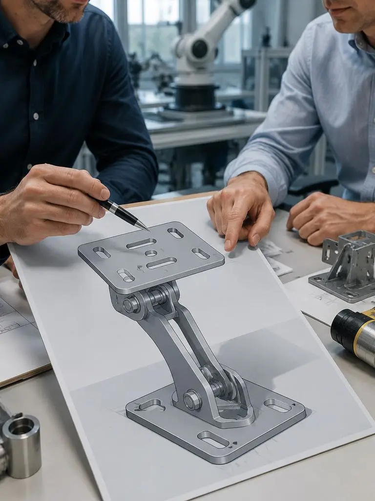
Create a CAD-style concept for an adjustable industrial sensor bracket. Include a rectangular mounting plate, four slotted mounting holes, a reinforced support arm, an adjustable hinge, and a circular sensor attachment point. Use a metal construction with rounded edges. Show the object in an isometric view on a neutral background. Make the fastener locations and installation direction easy to understand.
This prompt does not pretend that every dimension has already been calculated. Instead, it communicates the main design logic.
After Text to CAD AI generates the visual direction, the founder and engineer can review it together. They might notice that the arm is too long, the hinge blocks tool access, or the mounting slots need a different orientation.
Purchasing staff could also use the visual to begin a high-level discussion about materials or fabrication methods. However, they should not use it to order parts.
The engineer can then transfer the accepted decisions into a controlled CAD workflow. Consequently, the first formal model begins with a clearer brief and fewer hidden assumptions.
Scenario Two: Reviewing a Product Enclosure With a Client
Now consider an industrial designer working on a countertop appliance.
The client says the current enclosure looks too heavy. They want a softer front edge, more ventilation, and a rear panel that can be removed during maintenance. At the same time, marketing wants the product to remain compact and visually clean.
These requirements may conflict.
More ventilation can change the product’s appearance. A removable panel needs seams, fasteners, or clips. A smaller enclosure may reduce internal space. Therefore, a designer cannot solve the problem by responding only to the phrase “make it less bulky.”
Instead, the designer can use Text to CAD AI to explore distinct visual directions.
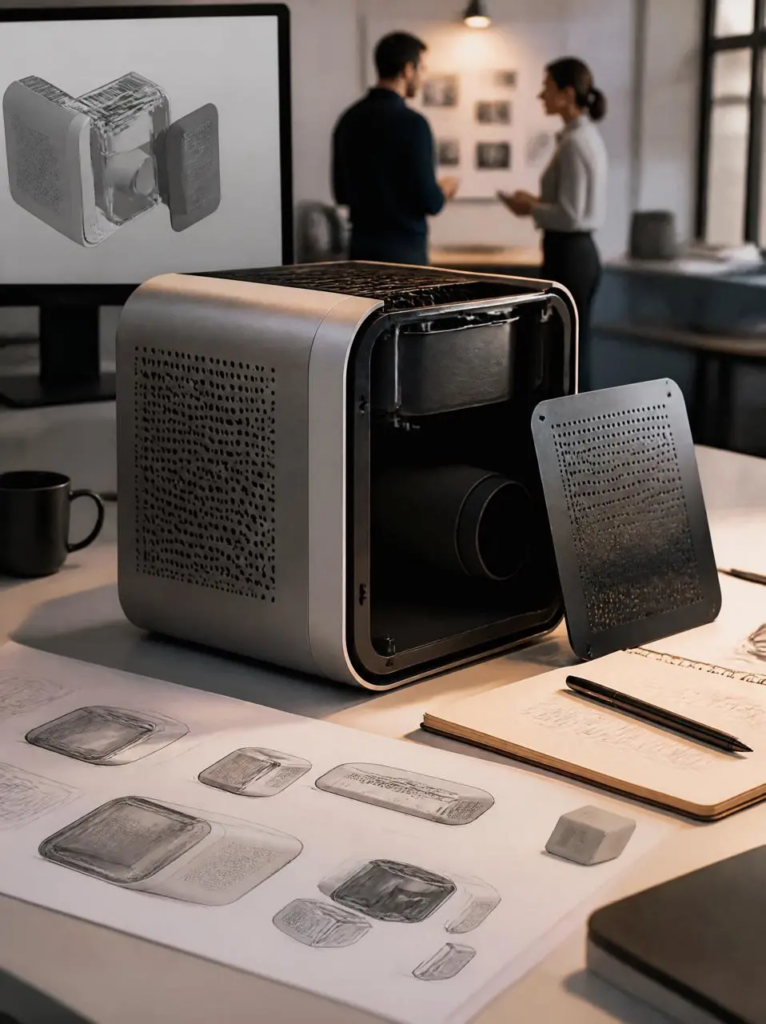
One concept might use a rounded front shell, hidden side vents, and a flush rear panel. Another might use a more technical enclosure with visible ventilation, clear panel seams, and easier service access.
When both directions are shown separately, the client can answer more useful questions:
- Which enclosure looks more compact?
- Are the ventilation openings too visible?
- Does the rear panel look easy to remove?
- Are the ports positioned where users can reach them?
- Does the exterior appear to leave enough internal volume?
- Which direction better fits the intended market?
The concept visual cannot confirm that all internal components will fit. Nevertheless, it gives design, marketing, and engineering teams a shared reference.
As a result, feedback becomes more specific. Instead of saying “make it cleaner,” the client can request smaller vent openings, a different panel seam, or a softer front radius.
What to Put in a Text to CAD AI Prompt
A useful prompt should not read like a mood board caption. It should explain why the object exists and which visible features support that purpose.
At the same time, the first prompt should not contain every possible manufacturing detail. Too much information can hide the design hierarchy.
A reliable prompt usually contains five layers.
Start With Function and Operating Context
First, explain what the object must do.
For example, a bracket may hold a sensor, connect to a machine frame, and allow vertical adjustment. An enclosure may protect electronics, release heat, and provide access for maintenance.
Next, describe where the object will be used. Mention whether it belongs on a desk, inside a factory, outdoors, or within another product.
You can also include known interactions:
- What connects to the object
- Who installs or operates it
- Whether it moves
- Whether it needs regular maintenance
- How much installation space is available
However, avoid inventing loads, temperatures, safety ratings, or environmental conditions when they are not known. Instead, separate confirmed requirements from assumptions.
Describe the Main Form
Next, define the object’s basic shape.
You might request a rectangular enclosure, an L-shaped support, a cylindrical housing, or a low-profile folding stand. This gives the visual a clear starting structure.
It also helps to describe proportion. Words such as compact, wide, shallow, tall, or low-profile can guide the general direction. Still, these terms are subjective. Therefore, add approximate measurements whenever proportion matters.
Name the Features That Matter
Text to CAD AI can visualize major structural features when they are clearly named.
Useful features may include:
- Holes
- Slots
- Ribs
- Bosses
- Vents
- Handles
- Hinges
- Fillets
- Openings
- Mounting surfaces
- Removable panels
- Fastener locations
Prioritize the features that affect function, assembly, or the product silhouette.
For instance, “add four mounting holes” is clearer than “make it easy to install.” Likewise, “include a removable rear panel” gives the concept a visible maintenance feature.
Still, the tool does not calculate whether those features are correctly sized or structurally sufficient. Their purpose is to communicate a direction for review.
Add Approximate Dimensions and Interfaces
Approximate dimensions help control proportion.
Use one consistent unit system. Then identify which measurements are critical and which are only illustrative.
For example:
Approximate base size: 120 × 80 mm. Overall height: about 160 mm. The hole pattern is illustrative and must be verified later.
Interfaces deserve special attention. Explain where the object attaches to another part, where cables enter, where a user grips it, or which panel must open.
Because generated measurements and labels may contain errors, never copy dimensions directly from the image into a production file. Instead, treat them as part of the visual brief.
Choose a Useful Technical View
Finally, select a view that answers the current design question.
An isometric view works well for overall form. A front elevation makes silhouette and hole placement easier to compare. An exploded concept can explain assembly order. Meanwhile, a section-inspired view can suggest internal relationships.
A close-up is more suitable when the discussion focuses on a hinge, port, mounting surface, or fastener location.
You can also request:
- A neutral background
- Controlled studio lighting
- Limited annotations
- Clear separation between components
- A technical presentation rather than a lifestyle scene
The goal is not to imitate a certified drawing. Instead, the view should make the most important relationship easy to understand.
How to Use Text to CAD AI Step by Step
Text to CAD AI works best as one stage in a larger design workflow. It should sit between the first written idea and formal engineering development.
The following process keeps the visual useful without confusing it with verified CAD data.
Step 1: Separate Requirements From Preferences
Begin by dividing the brief into two groups.
Requirements describe what the product must do. Preferences describe how the team would like it to look or feel.
For example, a removable rear panel may be a requirement. A softer front edge may only be a preference.
This separation matters because design reviews often fail when every comment appears equally important. A clear hierarchy gives Text to CAD AI a stronger basis for generating the first direction.
Step 2: Generate the First Visual Direction
Enter a structured description that includes function, form, major features, approximate dimensions, assembly context, material direction, and presentation view.
Then generate one clear concept direction.
Do not try to solve every engineering question in the first attempt. Instead, check whether the image communicates the object’s overall purpose and structure.
At this stage, ask simple questions:
- Does the concept resemble the intended object?
- Are the main components visible?
- Is the requested mounting direction understandable?
- Does the chosen view reveal the right features?
If the answer is no, revise the prompt before adding more details.
Step 3: Review Geometry and Access
Once the general concept is clear, review the visual with the people who will design, install, source, service, or approve the product.
Focus on relationships rather than decoration.
Check whether fasteners appear accessible. Look for blocked ports, awkward installation angles, limited maintenance access, or possible component conflicts.
Also examine proportion. A support may look too thin, an enclosure may appear too deep, or a handle may sit too close to another feature.
These observations are not engineering validation. However, they help the team identify which issues need formal investigation.
Step 4: Create a Distinct Revised Version
Keep the original concept separate. Then generate a new version with the requested changes.
For example, the team may ask for:
- A shorter support arm
- Wider mounting slots
- A lower enclosure
- Smaller ventilation openings
- A relocated cable port
- A more accessible rear panel
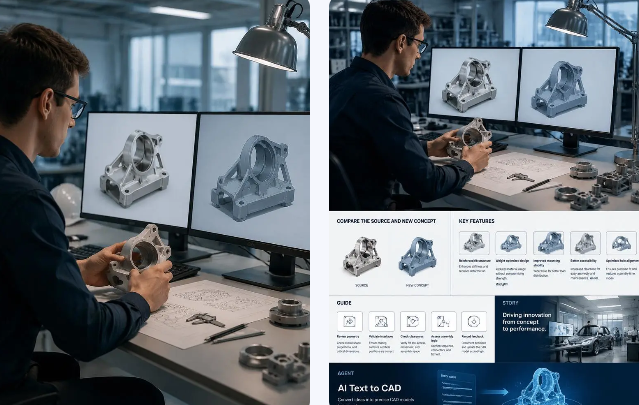
Place the original and revised images side by side. This makes changes in proportion, feature placement, and assembly logic easier to identify.
Avoid presenting an unchanged source image as a new result. Clear version separation supports better review and reduces confusion about which direction was approved.
Step 5: Rebuild and Validate in CAD Software
After the team chooses a promising direction, the concept must move into a professional engineering workflow.
A qualified designer should recreate it using constrained sketches, features, parts, assemblies, and drawings. They must then define or verify:
- Exact dimensions
- Fits and tolerances
- Material specifications
- Structural behavior
- Safety factors
- Installation clearances
- Ergonomics
- Manufacturing processes
- Relevant standards
- Maintenance requirements
Simulation and physical testing may also be necessary.
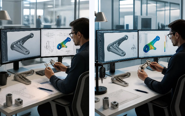
Only reviewed engineering files should guide procurement, tooling, construction, or production. The generated image remains a communication and ideation asset, not the authoritative design record.
What Text to CAD AI Cannot Replace
Text to CAD AI can make early discussions faster. However, speed does not remove the need for engineering responsibility.
The tool cannot confirm whether a product can carry a real load. It cannot prove that two parts fit together, that a hinge will survive repeated use, or that an enclosure meets electrical and thermal requirements.
It also cannot verify:
- Hidden internal geometry
- Exact scale
- Wall thickness
- Tool access
- Material strength
- Assembly sequence
- Surface finish
- Manufacturing cost
- Regulatory compliance
- Intellectual property risks
Therefore, generated concepts should be clearly labeled as visual concepts.
This label is especially important when images are shared with clients, suppliers, investors, or non-technical stakeholders. A polished CAD-style visual can look more complete than it really is.
Teams should also avoid adding realistic-looking tolerances, certifications, or test results unless those details have been professionally verified.
Used responsibly, the tool supports better questions. Used carelessly, it may create false confidence. The difference comes from how the output is presented and what happens after the review.
Better Questions to Ask During Concept Review
A weak design review asks whether the image looks good.
A stronger review asks whether the concept communicates the right product logic.
Instead of discussing only visual preference, teams can ask:
- Does the structure match the intended function?
- Can installers reach the fasteners?
- Are important interfaces visible?
- Does the product appear easy to maintain?
- Are moving parts likely to collide?
- Is the enclosure large enough for the expected components?
- Which features are essential?
- Which details are still assumptions?
- What must an engineer calculate next?
- What information is missing from the brief?
These questions turn the concept visual into a decision-making tool.
They also help non-technical stakeholders participate more effectively. A client may not understand parametric constraints, but they can identify an inaccessible panel or an awkward port position.
Meanwhile, engineers can explain which parts of the idea are feasible, which require calculation, and which need to change.
Therefore, Text to CAD AI is most useful when the image starts a better conversation rather than ending the design process.
Text to CAD AI FAQ
What does Text to CAD AI generate?
It generates CAD-style concept visuals based on natural-language design intent. The prompt can include function, form, major features, approximate dimensions, material direction, assembly context, and a preferred technical view.
Does Text to CAD AI create an editable CAD file?
Not automatically. A generated visual is not necessarily a STEP file, parametric model, technical drawing, or manufacturing dataset. A qualified professional must rebuild and verify the selected direction in suitable engineering software.
Which technical views can I request?
You can request an isometric view, front elevation, exploded concept, section-inspired presentation, or close-up of a critical feature. Choose the view according to the design question you need to discuss.
Who can use the tool?
Product managers, industrial designers, engineers, hardware founders, makers, educators, and clients can use it for early visualization. It is particularly helpful when technical and non-technical participants need a shared reference.
Can a generated concept be manufactured directly?
No. The geometry, materials, tolerances, structural behavior, safety, standards, and manufacturing process must be professionally reviewed before production.
Why should the original and revised concepts remain separate?
Separate images make design changes easier to see. They also help teams compare proportion, feature placement, interfaces, and assembly logic without confusing one version with another.
Build a Shared Visual Language Before the First Model
Early product development often slows down because people use the same words while imagining different objects.
A founder says “compact.” A client says “clean.” An engineer hears “easy to manufacture.” Meanwhile, the designer is still trying to understand which features are fixed and which can change.
Text to CAD AI gives those participants a shared visual starting point.
By describing function, form, features, approximate dimensions, interfaces, and technical views, teams can turn an abstract request into a CAD-style concept that is easier to question and refine.
The tool does not replace professional CAD modeling. Nor does it remove the need for calculations, testing, safety review, or manufacturing expertise.
Instead, it improves the handoff that happens before those steps.
A clear concept visual can expose assumptions, guide stakeholder feedback, document revisions, and help an engineer understand the intended direction before building the first formal model.
That is the real value of Text to CAD AI: not skipping engineering, but beginning engineering with a much clearer conversation.
Go to WeShop AI For Exploration: